

Jun . 06, 2025 19:42 Back to list
Precision Silica Sol Casting Solutions Custom & ODM Options
- Core process principles of silica sol investment casting
- Material properties comparison: Silica sol vs alternatives
- Commercial vendor analysis and benchmark data
- Customization workflows for specialized applications
- Aerospace turbine component implementation
- Medical implant manufacturing applications
- Industrial valve production case study
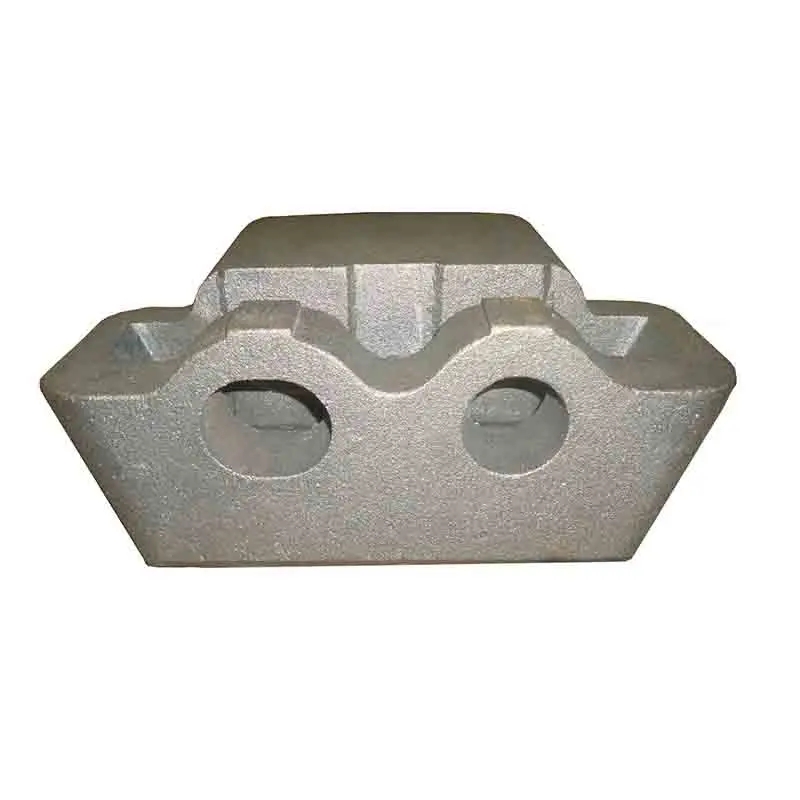
(silica sol casting)
Understanding Silica Sol Casting Processes
Silica sol casting, technically termed ceramic shell investment casting, utilizes colloidal silica binder systems to achieve remarkable dimensional accuracy. The process begins with injecting wax into aluminum dies, forming precise patterns that are assembled into clusters. These clusters undergo repeated dipping in ceramic slurries containing refractory materials like zircon flour and fused silica, followed by stuccoing with coarse ceramic grains. Each layer cures through ammonia vapor exposure, forming a thermosetting bond. After 6-9 coating cycles achieving 5-8mm shell thickness, dewaxing occurs via autoclave or flash fire methods. The final molds are fired at 870-1100°C before pouring 1560-1650°C molten alloys. Primary process advantages include:
- Surface finish capability: 1.6-3.2μm Ra compared to 12.5μm in sand casting
- Tolerance control: ±0.1mm per 25mm versus ±0.5mm in traditional methods
- Wall thickness potential: 0.75mm achievable compared to 3mm minimum in sand
Material Performance Metrics
Core material selection critically impacts casting integrity. The table below compares properties of silica sol against alternative binders:
| Property | Silica Sol | Ethyl Silicate | Sodium Silicate |
|---|---|---|---|
| Green Strength (psi) | 180-220 | 120-150 | 80-100 |
| Fired Strength (psi) | 900-1200 | 600-800 | 400-550 |
| Collapse Temperature (°C) | 1600-1750 | 1450-1550 | 1300-1400 |
| Thermal Expansion (μm/m·K) | 5.2-5.8 | 6.8-7.4 | 8.0-8.9 |
| Gas Permeability (cm2/Pa·min) | 15-20 | 8-12 | 4-7 |
Superior refractory stability enables silica sol systems to maintain dimensional integrity for nickel superalloys exceeding 1000°C operating temperatures. This binder demonstrates 35-40% lower thermal expansion than ethyl silicate alternatives, minimizing hot tearing in thin-section components. Permeability metrics allow adequate venting during high-speed filling operations over 1.2m/sec.
Commercial Provider Assessment
Technical capabilities vary significantly across casting suppliers. Premium providers demonstrate quantifiable advantages:
| Capability | Premium Tier | Standard Tier | Entry Level |
|---|---|---|---|
| Maximum Part Dimensions (mm) | 2200 x 1200 x 900 | 800 x 600 x 400 | 300 x 200 x 150 |
| Minimum Section Thickness (mm) | 0.5 ±0.05 | 1.2 ±0.15 | 2.0 ±0.3 |
| Surface Finish Ra (μm) | 1.6-3.2 | 3.2-6.3 | 12.5-25 |
| Certifications | AS9100, NADCAP, ISO 13485 | ISO 9001 | None |
| Material Traceability | Full PMI with 3.1/3.2 certs | Heat-level documentation | Batch documentation |
Premium providers maintain controlled dip rooms (22±1°C/50±5% RH) achieving process consistency impossible in facilities lacking environmental controls. Their vertical integration typically includes in-house pattern tooling, wax injection, metallurgy, and CNC finishing, providing 35-45% shorter lead times than multi-vendor approaches.
Customization Implementation Framework
Specialized applications require structured development methodologies. Phase 1 involves computational modeling of filling and solidification using MAGMASoft® or ProCAST® simulation platforms with proprietary algorithms optimized for silica sol systems. Phase 2 employs rapid pattern production via SLA or MJF additive manufacturing for prototype castings validated against predicted thermal gradients. Production tooling is developed following rigorous GD&T verification with CMM inspection at:
- Pattern tooling stage: ±0.05mm tolerances
- First casting validation: CT scan inspection at 50μm resolution
- Production sampling: Mechanical testing per ASTM E8/E21 standards
Defined wax injection parameters maintain dimensional stability: wax temperature 55±1°C, injection pressure 40-45 bar, dwell pressure 15 bar, cooling rate 2-3°C/minute. Process validation includes statistical capability analysis proving CpK >1.67 for critical features.
Aerospace Turbine Component Manufacturing
Leading aircraft engine manufacturers select silica sol investment casting for 76-82% of turbine components. GE Aviation's LEAP fuel nozzles demonstrate the technology's capabilities—these components feature:
- Internal channels with 0.8mm diameter and 8:1 aspect ratios
- Complex geometries replacing 20-piece assemblies with single-cast structures
- CMC interface surfaces requiring 0.025mm flatness tolerance
Production achieves 99.3% dimensional compliance across 1.2 million annual units using compensated tooling developed from CT scan analysis. The process reduces component weight by 25% versus fabricated assemblies while increasing temperature capability to 1149°C. Each casting is radiographed per ASTM E272 standards and undergoes penetrant inspection per AMS 2647 requirements.
Orthopedic Implant Fabrication
Medical manufacturers leverage silica sol casting
's biocompatibility advantages for ISO 5832-2 compliant cobalt chrome implants. Standard workflows include:
- Vacuum induction melting (VIM) under 10-2 mbar atmosphere
- Hot isostatic pressing (HIP) at 1190°C/1000 bar
- Solution annealing at 1220°C with controlled cooling
Finished implants display 580-640 HV hardness, UTS exceeding 900MPa, and fatigue strength >500MPa at 107 cycles. Critical porous coating interfaces maintain 200-400μm roughness with >95% pore interconnectivity verified through micro-CT. Quality documentation includes melt traceability to ingot heat numbers and full metallurgical analysis per ASTM F75 section 7 requirements.
Implementing Custom Silica Sol Casting Solutions
Industrial pump manufacturers achieved breakthrough cost reductions applying tailored silica sol approaches to stainless steel valve bodies. Original sand-cast components required 120 minutes CNC machining per part. Through coordinated pattern tooling modification and process optimization:
- Machining requirements decreased by 78% to 26 minutes per casting
- Material utilization improved from 48% to 88%
- Annual scrap reduced by $420,000 through dimensional stability improvements
Implementation followed a three-stage methodology: Digital process simulation identified optimal gating for directional solidification; Rapid prototyping validated thermal stress predictions within 7% accuracy; Production monitoring established strict SPC control over mold preheat temperatures (720±15°C) and pouring parameters (1550±10°C). Post-cast inspection documented consistent CTQ achievement: ±0.15mm positional tolerance, surface finish below 3.2μm Ra, 100% radiographic acceptance. This comprehensive approach highlights custom silica sol casting's value in mission-critical applications requiring precision and reliability.

(silica sol casting)
FAQS on silica sol casting
Here are 5 groups of FAQs in HTML format focusing on "silica sol casting" and related :Q: Where can I buy silica sol casting parts?
Q: Do you provide ODM silica sol casting services?
Q: What custom silica sol casting options are available?
Q: Why choose silica sol casting over other methods?
Q: What's the lead time for custom silica sol castings?
-
Wall Heat Exchanger Solutions for Industrial Efficiency | CASiting
NewsDec.09,2025
-
Water To Water Exchanger – Durable Heat Transfer Solutions for Industry | Casiting
NewsDec.09,2025
-
Water Tube Heat Exchanger Solutions for B2B Industrial Efficiency | Casiting
NewsDec.09,2025
-
Reliable B Line Heat Exchanger Solutions for Industrial Processes
NewsDec.09,2025
-
Premium Cast Iron Water Main Pipe for Robust Infrastructure
NewsAug.27,2025
-
A-Rated Cast Aluminum Boilers: High-Efficiency Condensing Gas & LPG
NewsAug.26,2025